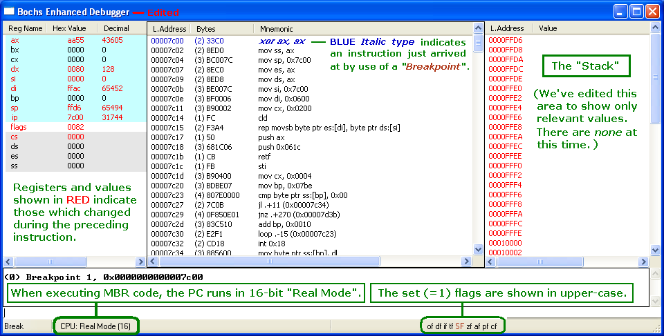
Bochs normally displays 32-bit registers, but we've edited the screen to show only 16-bit registers (like MS-DEBUG).
Your screen will also display an eflags register like this: id vip vif ac vm rf nt IOPL=0 of df if tf SF zf af pf cf
Pathways through the Windows 7 MBR
(with Notes for Using the "Bochs Enhanced
Debugger")
This Page is New and
Under Construction !!!
If you need any help in setting
up the Bochs Debugger, please email us.
This page describes each of the pathways that executing the Windows 7 MBR could possibly take, and what conditions might 'trigger' the code to go down one path or another. We will note where those decisions are made, so until you read otherwise, every instruction below will always be executed once the BIOS has loaded the MBR into Memory and transferred control of the PC's processor to it.
1. Copy the Code to Memory Locations 0x600 through 0x7FF
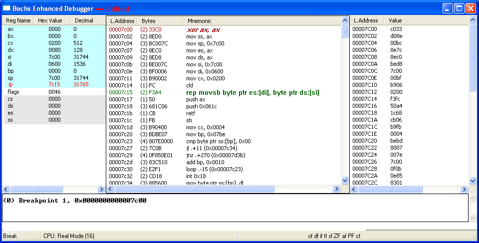
As we discussed on our Bochs Debugger page, Bochs will always "break" at the first instruction of its own BIOS code whenever it's run; which is also true when using the 'Enhanced Debugger,' so the first thing we need to do is ENTER: lb 0x7c00 and then a c in its command line (just above the word "Break" at the lower-left corner of the window). Once you ENTER the 'c' (to Continue), the Bochs BIOS will load the MBR code into Memory at 0x7c00 and wait for you to give it another command or press a key/button:
Bochs normally displays 32-bit registers, but we've edited the screen to show only
16-bit registers (like MS-DEBUG).
Your screen will also display an eflags register like this: id vip vif ac vm rf nt IOPL=0
of df if tf SF zf af pf cf
There's a great deal of information here! We're ready to execute the first MBR instruction in Memory at 0x7c00; code shown in BLUE italics indicates we have just arrived at a 'Breakpoint,' which will turn brown after being executed (all enabled Breakpoints are indicated by BROWN italic type). Among other things, the BIOS put AA55 in the AX register, 80h in the DL register, and left the Stack Pointer (SP) set to FFD6. Note: The CPU mode is always set to 16-bit REAL for execution of the MBR code. Only the SF (Sign) flag was set to 1; making it 'Negative' (flags register = 0082h). See our page on the 8086 CPU Registers (including how to interpret the "FLAGS" Register).
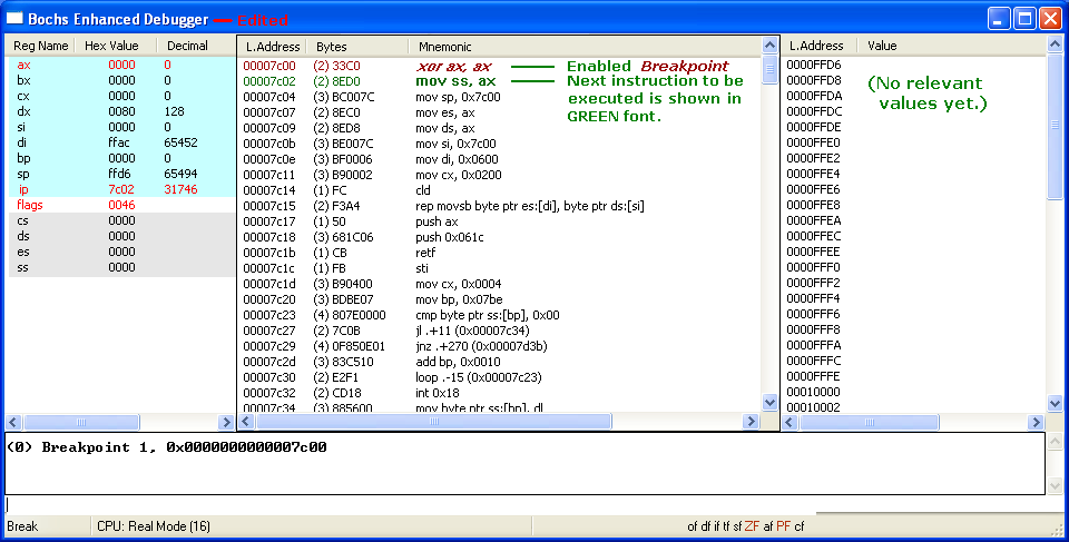
After entering an s on the command line to step into (execute) the first instruction, the one at 0x7c02 turns bold GREEN; indicating it will be the next instruction to be executed. Of course, the AX register was cleared to zero (by: xor ax,ax), the Sign flag was reset to 0 and both the ZF (Zero) and PF (Parity) flags have been set to 1 (flags register = 0046h):
mov ss, ax copies the zeros from AX into the Stack Segment (SS) Register; but it already was zero, so no real change there:
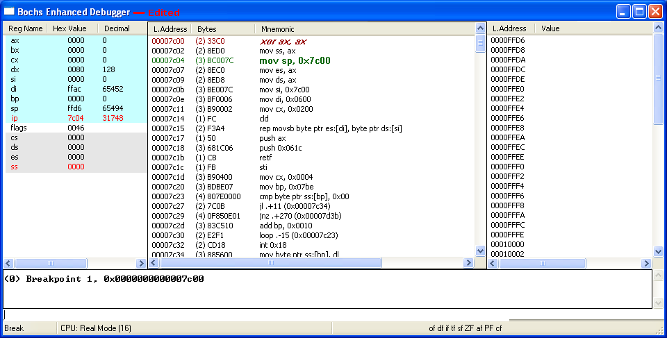
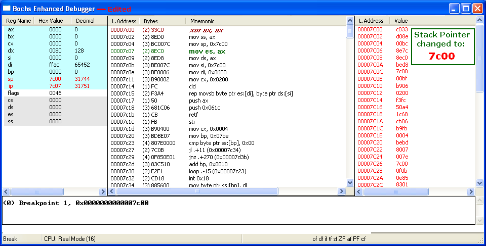
mov sp, 0x7c00 changes the Stack Pointer (SP) to 0x7c00, and you see all the bytes of the MBR sector we're executing show up there (in RED):
NOTE: From this point on, for instructions in which very little changes, we'll provide only the following 'simplified text display' which is similar to that of the old MS-DOS DEBUG screen (but it shows both the Bochs and DEGUB Flags names).
mov es,ax copies the zeros from AX into the ES (Extra Segment)
Register; which was already zero, so no real change in ES:

AX=0000  BX=0000  CX=0000  DX=0080  SP=7C00  BP=0000  SI=0000  DI=FFAC
DS=1B17  ES=0000  SS=0000  CS=0000  IP=7C09   of df if sf ZF af PF cf
7C09 8ED8          MOV     DS,AX              NV UP DI PL ZR NA PE NC

mov ds,ax copies the zeros from AX into the DS (Data Segment)
Register; which was already zero, so again no actual change:

AX=0000  BX=0000  CX=0000  DX=0080  SP=7C00  BP=0000  SI=0000  DI=FFAC
DS=0000  ES=0000  SS=0000  CS=0000  IP=7C0B   of df if sf ZF af PF cf
7C0B BE007C        MOV     SI,7C00            NV UP DI PL ZR NA PE NC

mov si,7c00 puts 7C00 into the Source Index (SI) Register, because
we want to copy all the code from 7c00 thru 7dff to a new location:

AX=0000  BX=0000  CX=0000  DX=0080  SP=7C00  BP=0000  SI=7C00  DI=FFAC
DS=0000  ES=0000  SS=0000  CS=0000  IP=7C0E   of df if sf ZF af PF cf
7C0E BF0006        MOV     DI,0600            NV UP DI PL ZR NA PE NC

mov di,0600 puts 0600 into the Destination Index (DI) Register, since
that's the new location in Memory we want to copy the MBR code to:

AX=0000  BX=0000  CX=0000  DX=0080  SP=7C00  BP=0000  SI=7C00   DI=0600
DS=0000  ES=0000  SS=0000  CS=0000  IP=7C11   of df if sf ZF af PF cf
7C11 B90002        MOV     CX,0200            NV UP DI PL ZR NA PE NC

mov cx,0200 puts 0200 (hex) into the Count Register (CX), in order
to copy all 512 (decimal) bytes of the code to locations 600 - 6ff:

AX=0000  BX=0000  CX=0200  DX=0080  SP=7C00  BP=0000  SI=7C00  DI=0600
DS=0000  ES=0000  SS=0000  CS=0000  IP=7C14   of df if sf ZF af PF cf
7C14 FC CLD NV UP DI PL ZR NA PE NC |
The Clear Direction (cld) instruction ensures the Direction Flag (df) is set to zero, so that any string operations will INCREMENT the SI and/or DI Registers; that is, count up rather than down (decrement), since we want to copy the code to increasing memory locations (not decreasing ones). But df was already zero (indicating up), so it doesn't change:
The Bochs Debugger disassembles the machine code bytes F3 A4 as: rep movsb byte ptr es:[di], byte ptr ds:[si], which helps us humans to understand this will REPeatedly copy a string of bytes, one byte at a time, from the location pointed to by the DS:SI (Data Segment:Source Index) registers to the location pointed to by the ES:DI (Extra Segment:Destination Index) registers. And from the previous instructions, we know it will do so for 512 times (CX=0200), in an upwards direction. (See our notes on the REP Instruction in Microsoft's MBR code for some side details.)
The following shows how executing this rep movsb instruction in a step-by-step manner would take 512 steps! We're going to step through only the first four and finish with the last four (showing only 8 of the 512 steps). The CX register decrements, and the SI and DI registers will increment. The previous step copied the byte 33h from 7c00 to 0600 and each successive step will copy another of the MBR; until all 512 bytes are copied:
AX=0000  BX=0000  CX=01FF  DX=0080  SP=7C00  BP=0000  SI=7C01  DI=0601
DS=0000  ES=0000  SS=0000  CS=0000  IP=7C15   of df if sf ZF af PF cf
7C15 F3            REP                        NV UP DI PL ZR NA PE NC
7C16 A4            MOVSB

AX=0000  BX=0000  CX=01FE  DX=0080  SP=7C00  BP=0000  SI=7C02  DI=0602
DS=0000  ES=0000  SS=0000  CS=0000  IP=7C15   of df if sf ZF af PF cf
7C15 F3            REP                        NV UP DI PL ZR NA PE NC
7C16 A4            MOVSB

AX=0000  BX=0000  CX=01FD  DX=0080  SP=7C00  BP=0000  SI=7C03  DI=0603
DS=0000  ES=0000  SS=0000  CS=0000  IP=7C15   of df if sf ZF af PF cf
7C15 F3            REP                        NV UP DI PL ZR NA PE NC
7C16 A4            MOVSB

AX=0000  BX=0000  CX=01FC  DX=0080  SP=7C00  BP=0000  SI=7C04  DI=0604
DS=0000  ES=0000  SS=0000  CS=0000  IP=7C15   of df if sf ZF af PF cf
7C15 F3            REP                        NV UP DI PL ZR NA PE NC
7C16 A4            MOVSB
==============================================
At this point we switch to the last four steps:
==============================================
AX=0000  BX=0000  CX=0004  DX=0080  SP=7C00  BP=0000  SI=7DFC  DI=07FC
DS=0000  ES=0000  SS=0000  CS=0000  IP=7C15   of df if sf ZF af PF cf
7C15 F3            REP                        NV UP DI PL ZR NA PE NC
7C16 A4            MOVSB

AX=0000  BX=0000  CX=0003  DX=0080  SP=7C00  BP=0000  SI=7DFD  DI=07FD
DS=0000  ES=0000  SS=0000  CS=0000  IP=7C15   of df if sf ZF af PF cf
7C15 F3            REP                        NV UP DI PL ZR NA PE NC
7C16 A4            MOVSB

AX=0000  BX=0000  CX=0002  DX=0080  SP=7C00  BP=0000  SI=7DFE  DI=07FE
DS=0000  ES=0000  SS=0000  CS=0000  IP=7C15   of df if sf ZF af PF cf
7C15 F3            REP                        NV UP DI PL ZR NA PE NC
7C16 A4            MOVSB

AX=0000  BX=0000  CX=0001  DX=0080  SP=7C00  BP=0000  SI=7DFF  DI=07FF
DS=0000  ES=0000  SS=0000  CS=0000  IP=7C15   of df if sf ZF af PF cf
7C15 F3            REP                        NV UP DI PL ZR NA PE NC
7C16 A4 MOVSB |
NOTE: You can skip all 512 single steps above by simply entering: lb 0x7c17 and then c at the Command line; which will take you directly to the following instruction.
The following shows the results of executing the last step above (the CX register becomes zero, so we can move on to the next group of instructions which will push data onto the Stack):
AX=0000  BX=0000  CX=0000  DX=0080  SP=7C00  BP=0000  SI=7E00  DI=0800
DS=0000  ES=0000  SS=0000  CS=0000  IP=7C17   of df if sf ZF af PF cf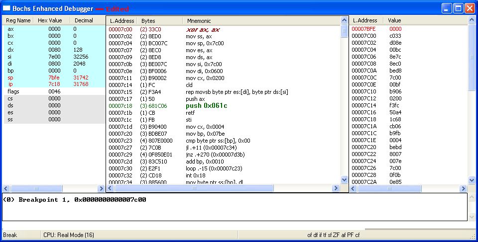
7C17 50 PUSH AX NV UP DI PL ZR NA PE NC |
The next two screens show the zero bytes of the AX register and the Word 0x061c being pushed onto the Stack:
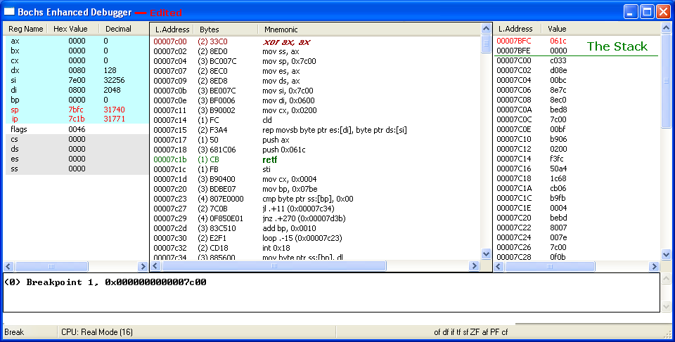
And with the execution of the retf (Return Far) instruction, both the Words we pushed onto the Stack are removed from it, and we begin executing the next instruction at its new location of 0000:061C (the whole sector having been copied to 0x600 through 0x7FF).
2. Checking for an 'Active'1 Partition
After starting your Bochs Debugger session on an image file with a Windows 7 MBR sector, you can of course, jump right to the following display, by entering: lb 0x61c and then c at the Enhanced Debugger's Command line:
AX=0000  BX=0000  CX=0000  DX=0080  SP=7C00  BP=0000  SI=7E00  DI=0800
DS=0000  ES=0000  SS=0000  CS=0000  IP=061C   of df if sf ZF af PF cf
061C FB STI NV UP DI PL ZR NA PE NC |
The sti (Set Interrupt Flag) sets this bit (IF = 1) in the Flags Register, enabling interrupts; MS-DEBUG's flag indicator will change from "DI" (Disable Interrupts) to "EI" (Enable Interrupts). This means the processor begins responding to external, maskable interrupts after the next instruction is executed. Apart from other changes noted in the following instructions, the hex Word for the Flags Register becomes: 0246.
AX=0000  BX=0000  CX=0000  DX=0080  SP=7C00  BP=0000  SI=7E00  DI=0800
DS=0000  ES=0000  SS=0000  CS=0000  IP=061C   of df IF sf ZF af PF cf
061D B90400        MOV     CX,0004            NV UP EI PL ZR NA PE NC

mov cx,0004 changes the Count (CX) Register; so if needed, all four
Partition Table entries will be checked for the Active indicator (80h):

AX=0000  BX=0000  CX=0004  DX=0080  SP=7C00  BP=0000  SI=7E00  DI=0800
DS=0000  ES=0000  SS=0000  CS=0000  IP=0620   of df IF sf ZF af PF cf
0620 BDBE07        MOV     BP,07BE            NV UP EI PL ZR NA PE NC

mov bp,07be puts 07be into the Base Pointer (BP) Register, so we can
check for 80h at the correct offset in each of the 4 P. Table entries:

AX=0000  BX=0000  CX=0004  DX=0080  SP=7C00  BP=07BE  SI=7E00  DI=0800
DS=0000  ES=0000  SS=0000  CS=0000  IP=0623   of df IF sf ZF af PF cf
                                              NV UP EI PL ZR NA PE NC
0623 807E0000 CMP BYTE PTR [BP+00],00 SS:07BE=80 |
This multi-byte CMP (CoMPare) instruction compares the value at the Memory location pointed to by the SS:BP registers and
the given value (Zero), by: Subtracting the second operand (the Zero) from the first operand (that value in Memory), then setting or clearing bits in the
Flags Register according to the rules for Subtraction (see How Flags are Set for more details). The only difference
between this CMP instruction and its corresponding SUB instruction ("80 6E 00 00") is that the Subtraction operation will also store the result
in the first operand.
The first byte in each of the four possible 16-byte Partition Table entries indicates
whether that partition is the Active partition or not. If, as in the case of most Windows™ OS installs, the Active partition is the first one,
then Memory location 0x7be will contain an 80 hex byte (as shown above); which results in the following:
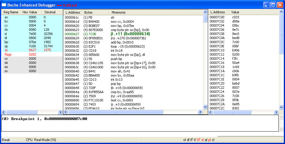
Since 80h (at 0x7be) - 0 = 80h, the highest bit (bit 7) is a 1, so the Sign Flag is set (SF=1). The Zero Flag is reset (zf=0) since the result is not all zero bits, and the Parity Flag is also reset (pf=0) since there's only one 1's bit (an odd number) in the result; all other flags are unaffected. (Note: Any byte with its highest bit set indicates a Negative number and 2's Complement arithmetic; as explained on our 2-Byte Jumps page, must be used).
Take the following links to see what happens if:
A. The MBR finds a 01 through 7Fh byte
B. The MBR finds only zero bytes (No Active Entry)
C. The Last Partition is Active (No entry problems)
D. The MBR finds an 81h through FFh byte
E. Continue with First Entry as Active (80h in 0x7be):
The CMP instruction (just like Subtraction) uses signed bytes (80h actually represents a negative 128), thus the reason the comparison results in a LESS THAN condition; or expressed differently: Whenever SF (Sign Flag) is not equal to OF (Overflow Flag). So, execution jumps (forward; "+") by 11 bytes, to location 0x634:
AX=0000  BX=0000  CX=0004  DX=0080  SP=7C00  BP=07BE  SI=7E00  DI=0800
DS=0000  ES=0000  SS=0000  CS=0000  IP=0634   of df IF SF zf af pf cf
                                              NV UP EI NG NZ NA PO NC
0634 885600 MOV [BP+00],DL SS:07BE=80 |
More will be posted in the near future... this page is still Under
Construction !!!
If you need any help in setting up the Bochs Debugger, please email us.
1[Return to Text] The official Windows 7 OS install DVD creates 2 partitions on an un-partitioned drive: The first is labeled "System Reserved" (with a capacity of 100 MiB); it is set to be the Active partition (Active meaning the partition which 'boots-up' first; there can only be one of these). The other (largest) partition, contains the Windows 7 OS and is set with the drive letter C: and is also listed as the Boot partition as can be seen in Disk Management:
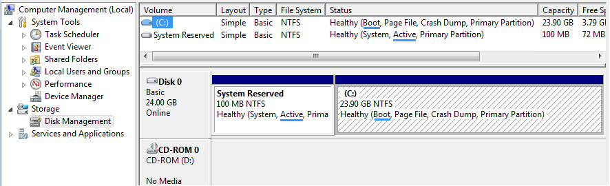
Disk Management view of small 25 GB Win 7 OS drive. The terms Active and Boot no longer refer to the same partition.
The term Boot refers to the partition which contains the operating system which will boot-up; not the first "Boot Sector" that is loaded into Memory and executed, which in this case actually comes from the Active partition. [Return to Text]
Date Page Added: May 19, 2013 (19.05.2013).
Updated: May 20, 2013 (20.05.2013); May 26, 2013 (26.05.2013); May 27, 2013 (27.05.2013); June 28, 2013 (28.06.2013).
Last Updated: July 5, 2013 (05.07.2013).
You can write to us using this:
online reply form.
(It opens in a new window.)
![]() The Starman's x86 ASSEMBLY Pages
The Starman's x86 ASSEMBLY Pages
![]() The Starman's Realm Index Page
The Starman's Realm Index Page